
Power board for tattoo removal devicesND-YAG / Q-SWITCH POWER
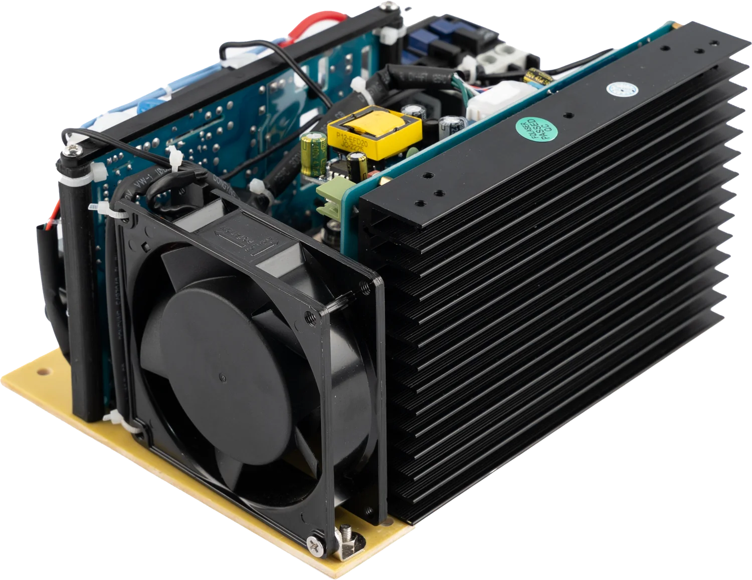
The power board of Q-switched ND-YAG tattoo removal and carbon peeling devices. It builds up the high-voltage energy the lamp needs, manages the trigger timing and safely discharges that energy when the device is switched off.
220 V ACInput
100 µF / 1400 VPulse capacitor
Charge · simmer · triggerFunction
Open frame, OEMForm
Product capability
Power electronics engineered for system integration.
Charging, triggering and safe discharge on one board.
ND-YAG and Q-Switch are not separate products; they are two parts of the same device. This board covers both the energy and the lamp-trigger side of a tattoo removal device.
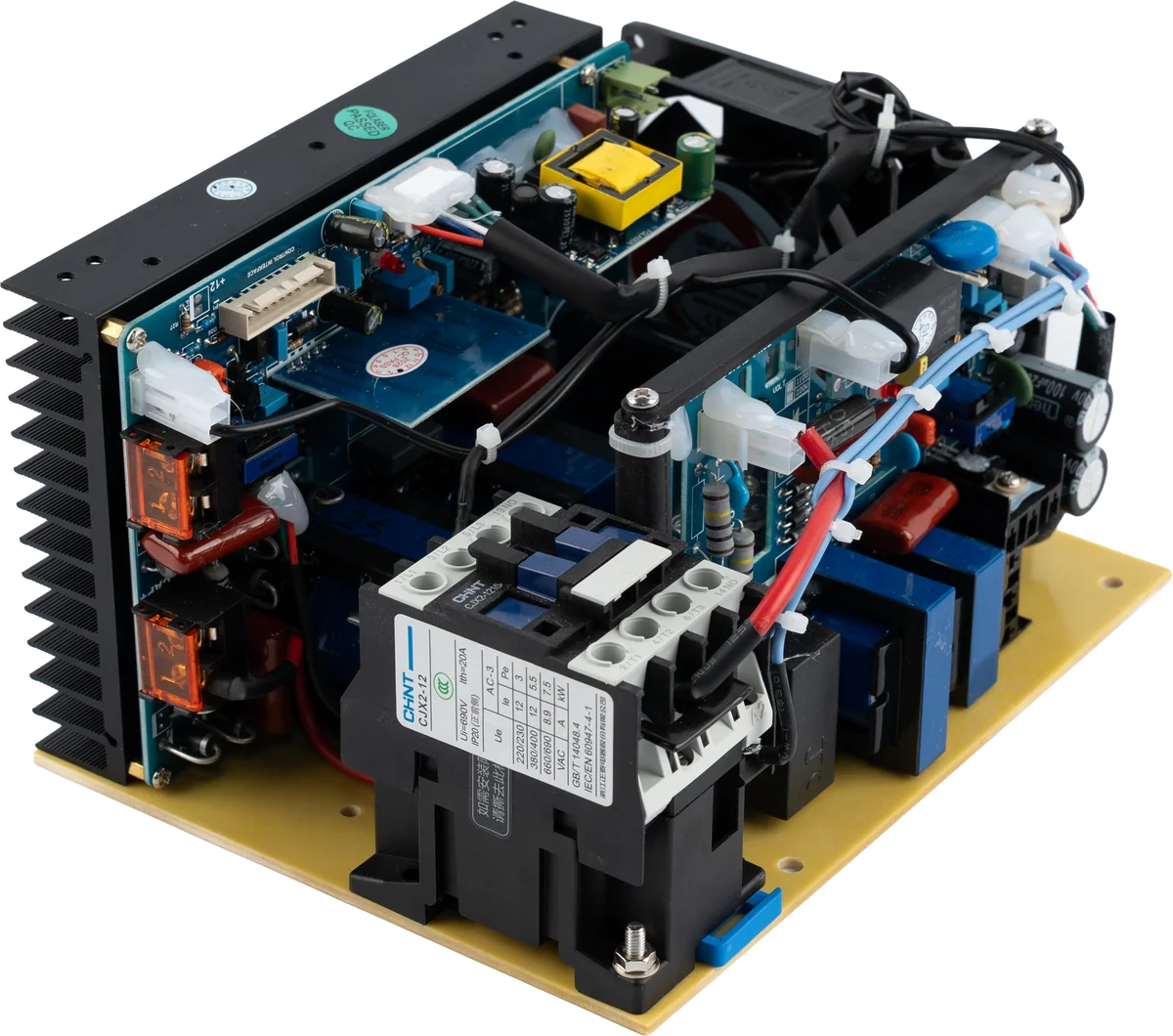
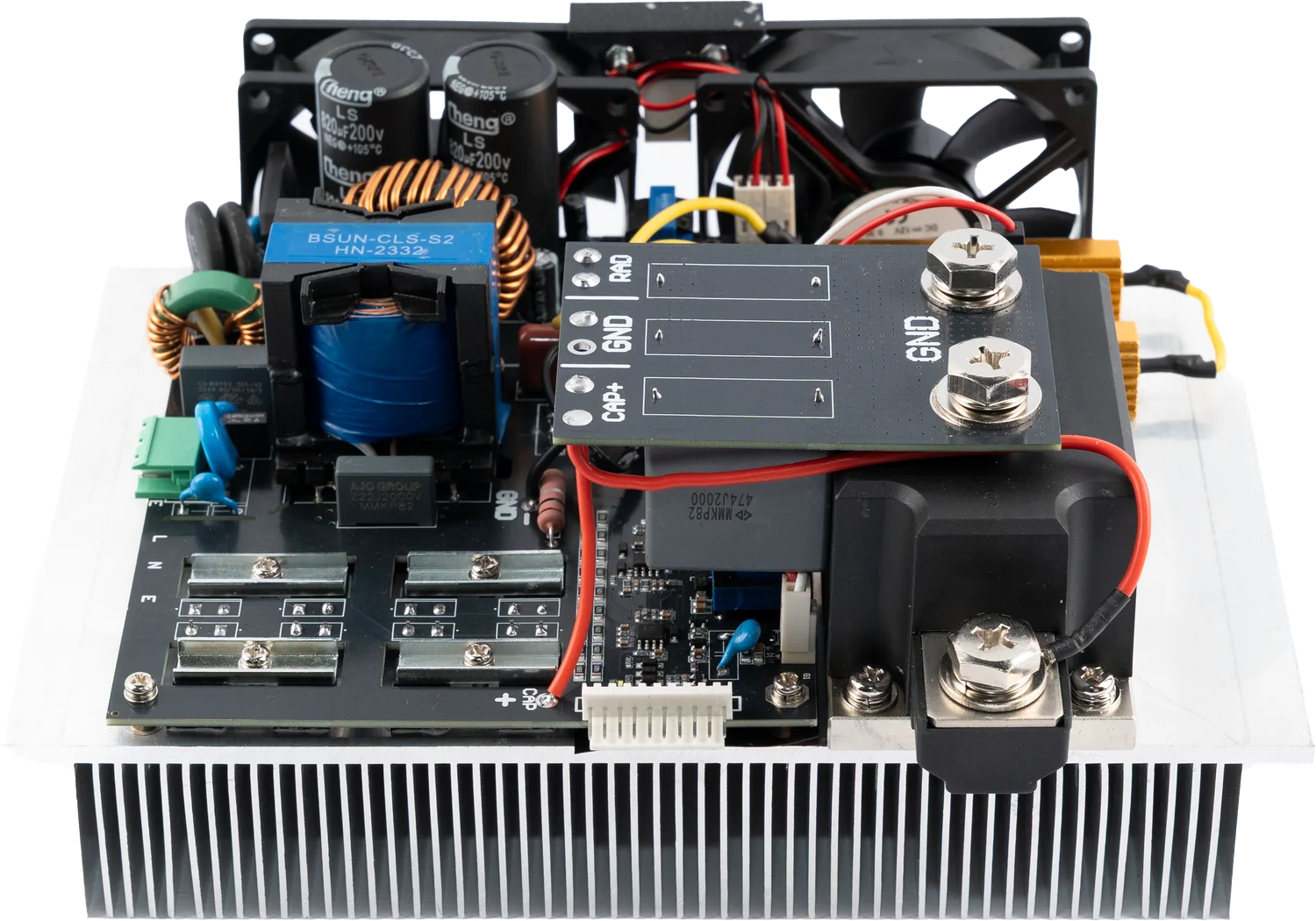
The open-frame board seen from above. Charging stage, trigger circuit and the contactor that manages the energy path share one chassis.
Inside the unit
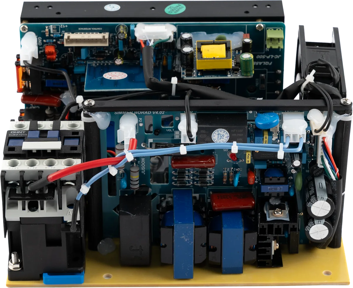
What is inside the enclosure?
Photographs show an actual unit from the production line.
Connections and terminals
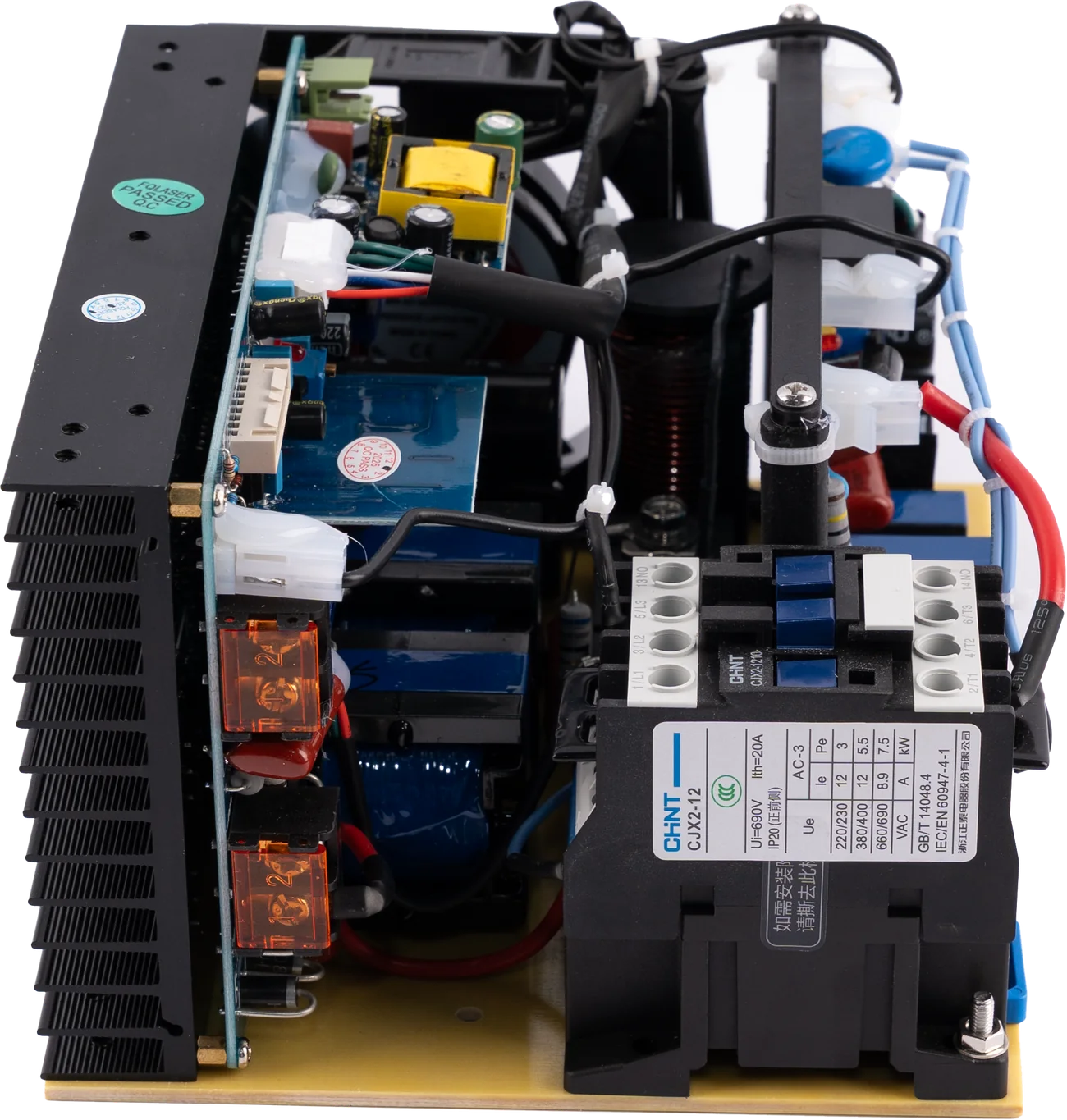
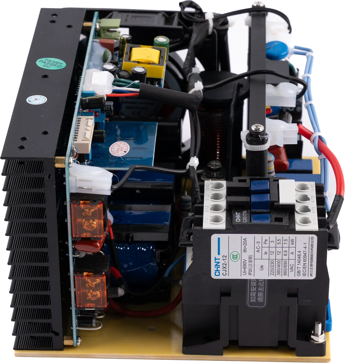
How does it connect to the system?
The board ships open-frame; the connection layout is planned together, around the internal design of your device. The numbers mark the connection zones on the board and match the numbers in the connection diagram below.
1234- Mains input (line / neutral)220 V AC supply. Line (brown) goes to the L terminal and neutral (blue) to the N terminal; the two must not be swapped. As the board is open-frame, protective earthing runs through the device chassis.
- Control interfaceLink to the device controller. Charge command, pulse energy reference, simmer, lamp triggering and Q-switch timing all run over this line; charge and ready states are read back through the same interface.
- Capacitor connection (CAP+ / CAP−)The capacitor supplied with the board is charged to high voltage through these terminals. It is a high-voltage component: complete discharge must be verified at device level before service.
- Applicator outputThe switched output feeding the handpiece. On each pulse the capacitor discharges into the flash lamp through this terminal and the shared negative terminal.
Connection diagram
How do energy and triggering flow?
Follow, step by step, where ND-YAG / Q-SWITCH POWER sits inside your device. The numbers mark the connection areas on the board.
1 / 5
Functions carried on the control interface
- Chargehigh-voltage charge command
- Energy referencepulse energy level
- Simmerlamp kept conductive
- Lamp triggerpulse trigger
- Q-switchpulse timing
- Feedbackcharge and ready status
The diagram is simplified to explain system integration; it does not show the internal circuitry of the board. Interface signals, cable cross-sections, protective devices and the final operating point are defined per project once the lamp, capacitor and device architecture are verified.
Technical architecture
ND-YAG / Q-SWITCH POWER technical specifications
Electrical values
- Input voltage
- 220 V AC · line + neutral
- Input frequency
- 50-60 Hz
- Pulse capacitor
- 100 µF ±5% / 1400 V DC · film · 1 piece
- Pulse energy
- ≤98 J at 1400 V (theoretical maximum)
- Charge voltage
- Below the capacitor rating, set per project
- Auxiliary supply
- Isolated module · +12 V DC control rail
Pulse and trigger chain
- Trigger architecture
- Simmer and lamp trigger on one board
- Simmer
- Lamp held conductive at low current
- Energy control
- Set by charge voltage; energy scales with its square
- Energy path
- Contactor · AC-3 12 A / 3 kW · IEC/EN 60947-4-1
- Control interface
- Charge, energy reference, simmer, trigger, Q-switch
- Repetition rate (device)
- Typically 1-10 Hz in the application
Safety, cooling and OEM
- Controlled discharge
- Energy removed at shutdown and for service
- Cooling
- Fan-cooled heatsink block
- Earthing
- Through the device chassis, verified at device level
- Q-switch driver
- Separate unit; timing synchronised from this board
- Delivery form
- Open-frame board with capacitor
- Document scope
- CE · EMC · LVD (TS EN 60335-1)
The values in this table come from three sources. First, the ratings of the components actually used in the product: the pulse capacitor, the contactor that switches the energy path and the input class. Second, quantities calculated directly from those ratings, such as the energy a 100 µF capacitor holds at 1400 V. The capacitor is a film type rather than an electrolytic precisely so that it withstands repeated high-current lamp discharges. Third, the rows marked "device", which give the typical operating range of the Q-switched ND-YAG devices this board feeds. A model-specific user manual and test report for ND-YAG / Q-SWITCH POWER have not been published yet; the guaranteed operating point is defined per project once the lamp, capacitor and device architecture are verified.
Integration
Planned around your device architecture.
01
Lamp and energy matching
Lamp type, operating voltage, pulse energy and capacitor are evaluated together.
02
Timing chain
Charge, simmer, lamp trigger and Q-switch timing are aligned with the device controller.
03
Safety
Interlock, controlled discharge, service delay, grounding and high-voltage insulation are verified at device level.
Model family
ND-YAG / Q-SWITCH POWER product family
This product is offered as a single configuration; output values are engineered around your device architecture.
ND-YAG / Q-SWITCH POWER
One power board for Q-switched ND-YAG tattoo removal devices
OEM configuration
Engineered around the lamp, capacitor and device architecture
What ships with it
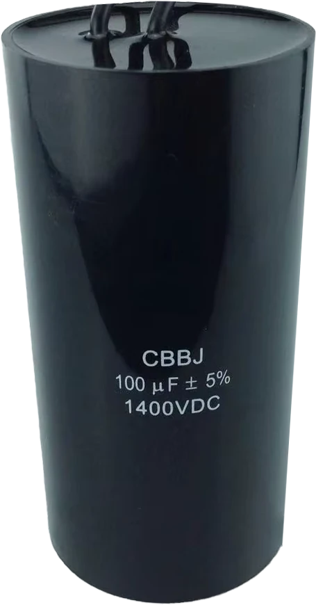
One capacitor is supplied with the board.
The energy needed for the lamp pulse is collected in this capacitor. The board charges it under control and manages the discharge at the trigger moment.
- Type
- Film, pulse discharge type (CBBJ)
- Capacitance
- 100 µF ±5%
- Voltage
- 1400 V DC
- Stored energy
- 98 J at 1400 V
- Quantity
- 1 piece
This component carries high voltage; inside the device it must sit apart from the control section and remain accessible so that it can be discharged safely during service.
Quality and documents
Verified product documentation.
Document scope is checked against the model and configuration. Current copies are shared on request.
Verified
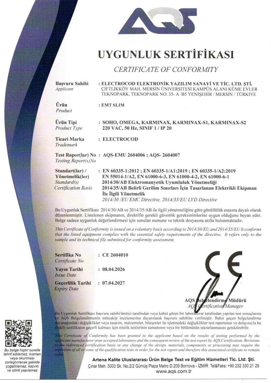
CE certificate of conformity
CE 2604010 · issued 08.04.2026 · valid to 07.04.2027 · scope: EMT SLIM · SOHO, OMEGA, KARMINAX, KARMINAX-S1, KARMINAX-S2
Verified
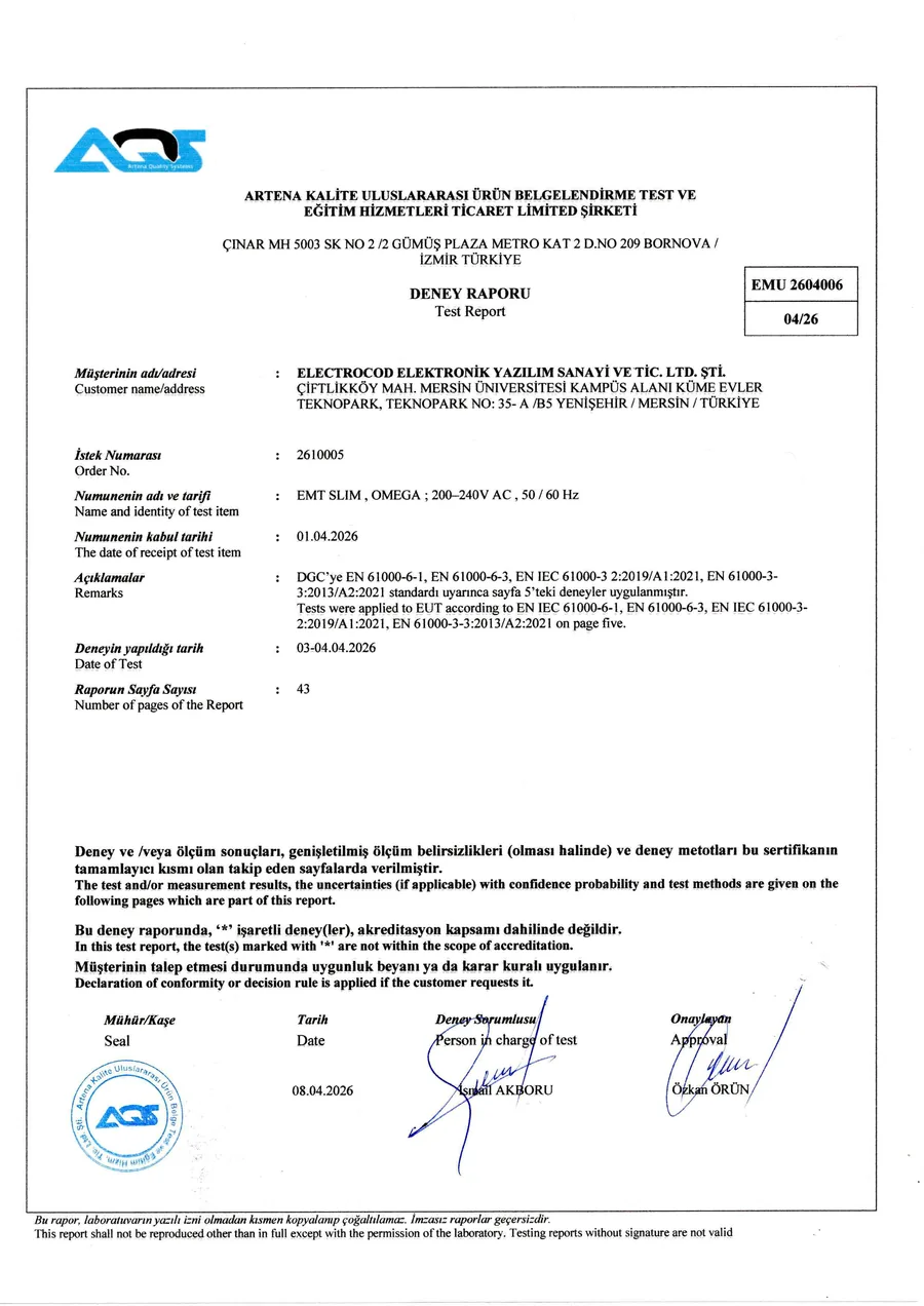
EMC test report
AQS-EMU 2604006 · 43 pages · emission and immunity tests passed
Verified
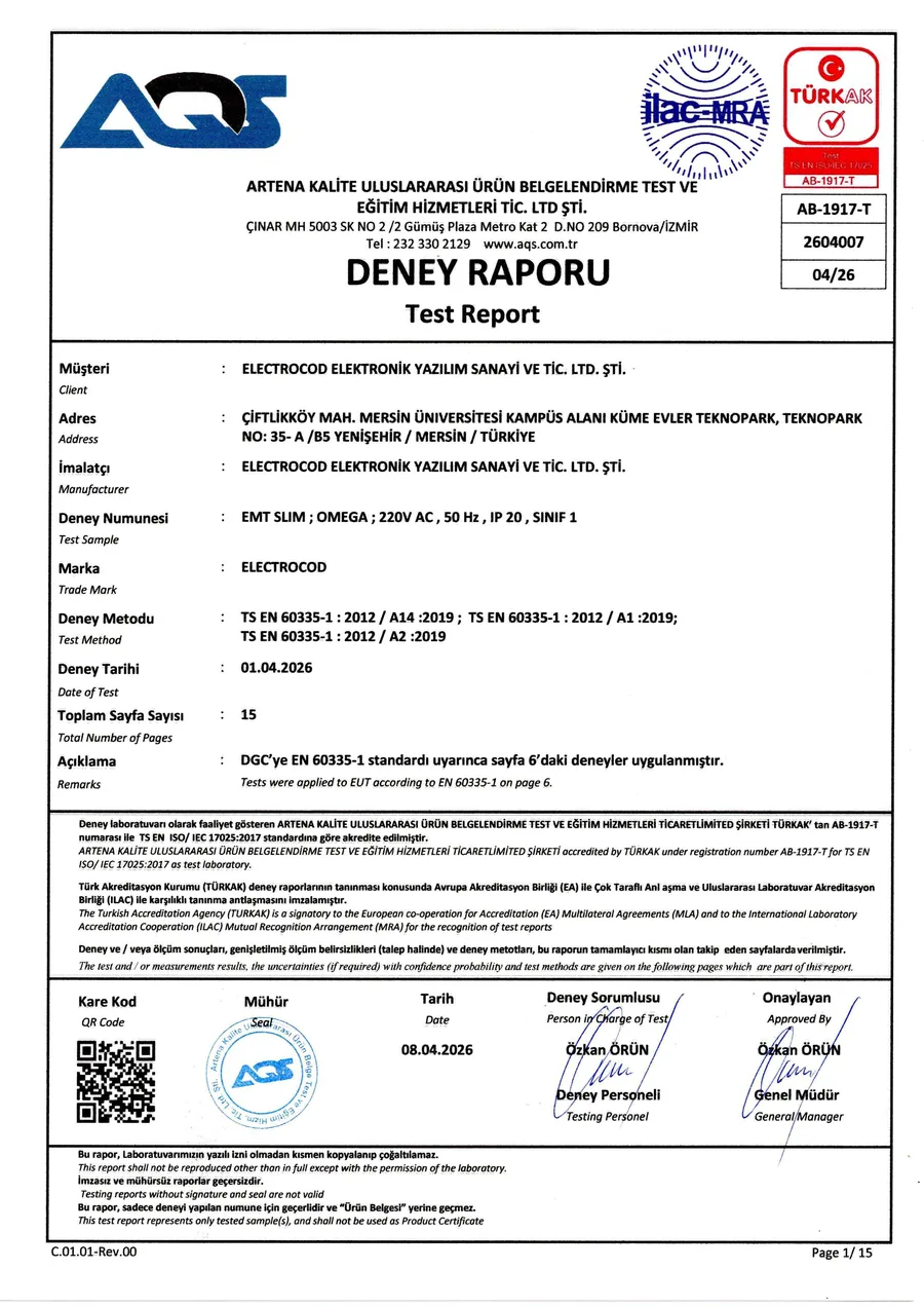
LVD test report
AQS-2604007 · 15 pages · TS EN 60335-1 · TÜRKAK accredited laboratory
Verified
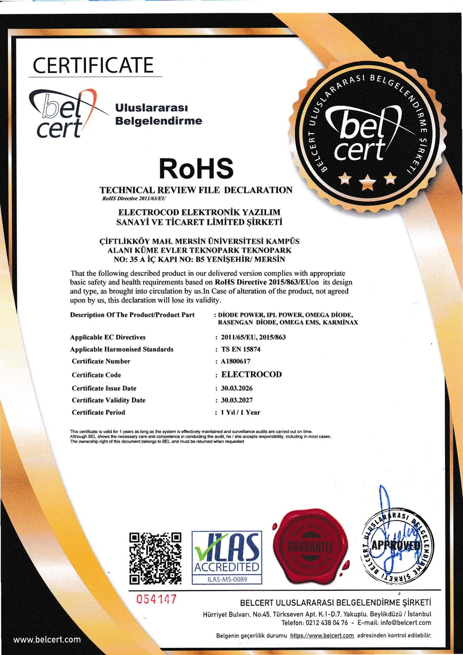
RoHS declaration
A1800617 · technical file declaration under 2011/65/EU and 2015/863
Frequently asked
What buyers ask before integration
Is the Q-switch driver on the board?
No. The Q-switch driver is a separate unit; this board synchronises its timing. The board itself carries the high-voltage charging circuit, the simmer circuit and lamp triggering together — so you do not need two separate boards for energy and triggering.
What happens to the capacitor energy when the device is switched off?
The board performs a controlled discharge at shutdown and during service, so the energy is released safely. Interlock, service waiting time, earthing and high-voltage isolation are verified at device level. On a board working at high voltage this is the most critical safety topic.
Does simmer require a separate board?
No. The simmer circuit sits on the same board. Because the lamp is held conductive at low current, triggering at the moment of the pulse is stable and repeatable, which protects both shot-to-shot consistency and lamp life.
What is the pulse energy?
The pulse capacitor is a 100 µF ±5% / 1400 V DC film type; at 1400 V the theoretical upper limit is 98 J. The actual charging voltage stays below the capacitor class and is set per project. Lamp type, operating voltage and target pulse energy are reviewed together.
Other products
Explore the other power families
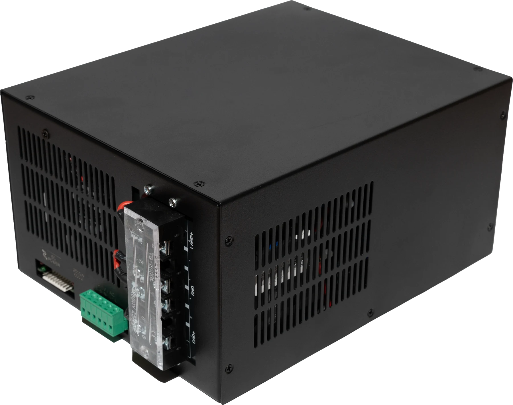 IPL POWER
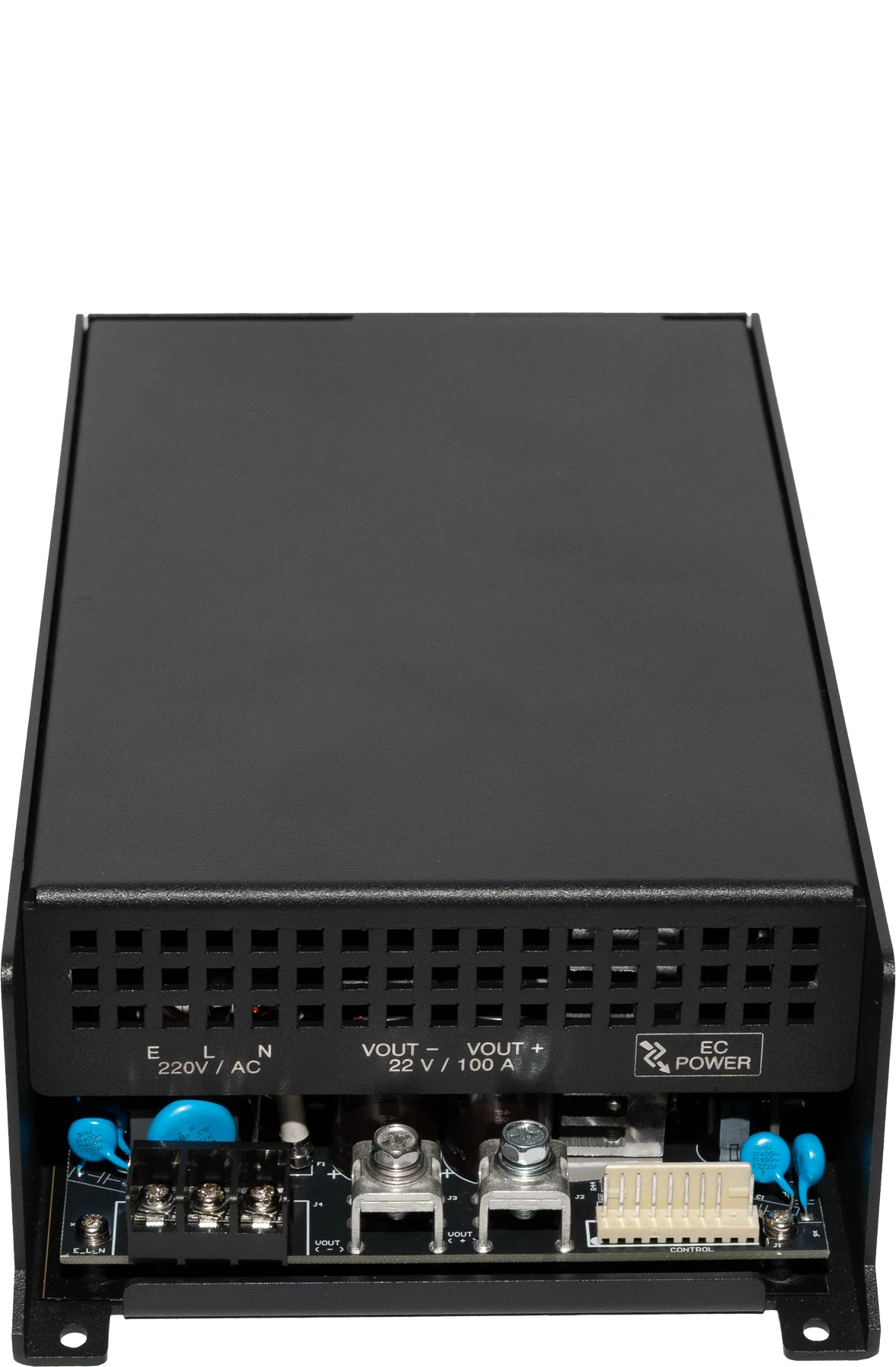 DIODE POWER
 EMS POWER
Let us define the right power architecture for your device.
Share the device type, target values and quantity. Our technical team will respond with the suitable product and integration options.