
Power unit for IPL and SHR devicesIPL POWER
The power source of hair removal and skin care devices built on IPL technology. It charges the capacitor and delivers the energy the xenon lamp needs to fire its light pulse.
200-240 V ACInput
200-400 V DCOutput
400-600 APeak current
1200-2000 WOutput power
Product capability
Power electronics engineered for system integration.
It charges the capacitor and fires the lamp.
In an IPL device the light pulse comes from energy stored in a capacitor and released into the xenon lamp. ECP-2000 handles both jobs in one unit: it stores the energy at an adjustable voltage and fires the pulse on command from the device controller.
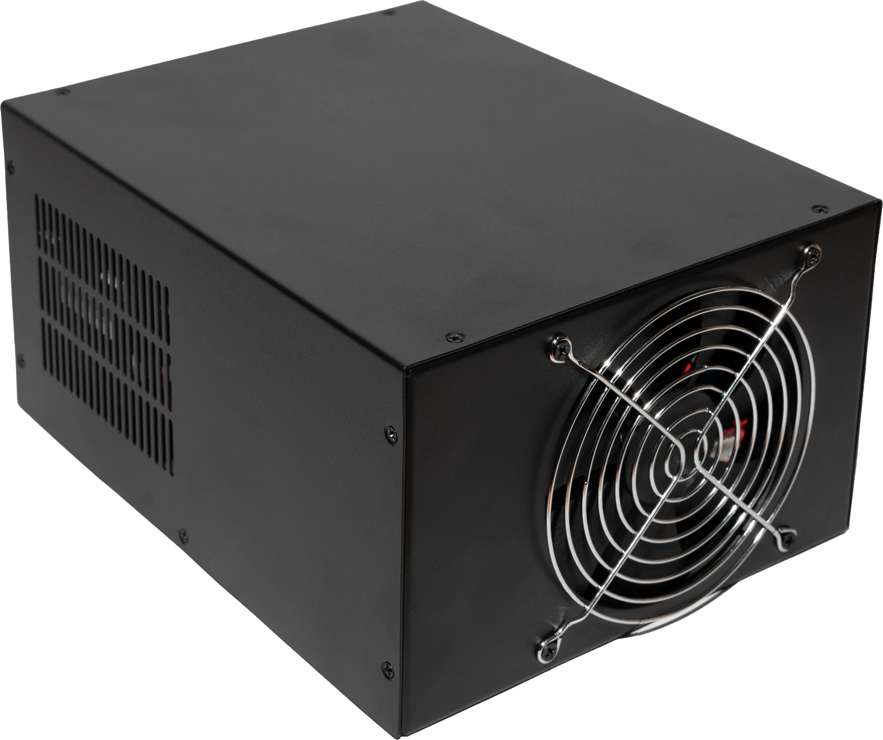
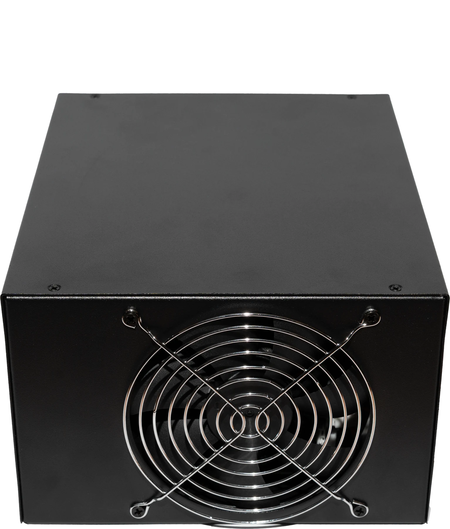
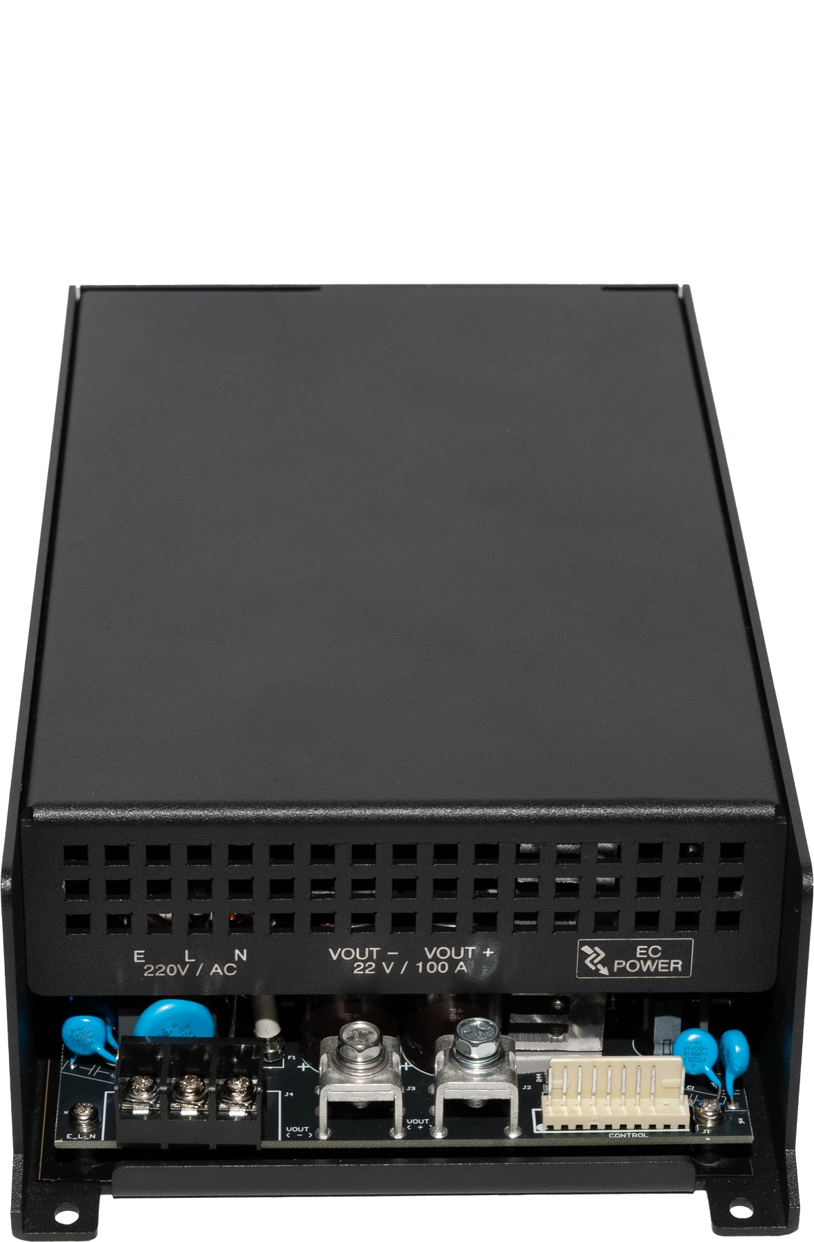
The closed enclosure. Every terminal and the control interface sit on the rear panel.
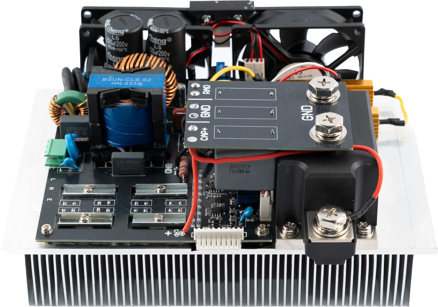
Inside the unit
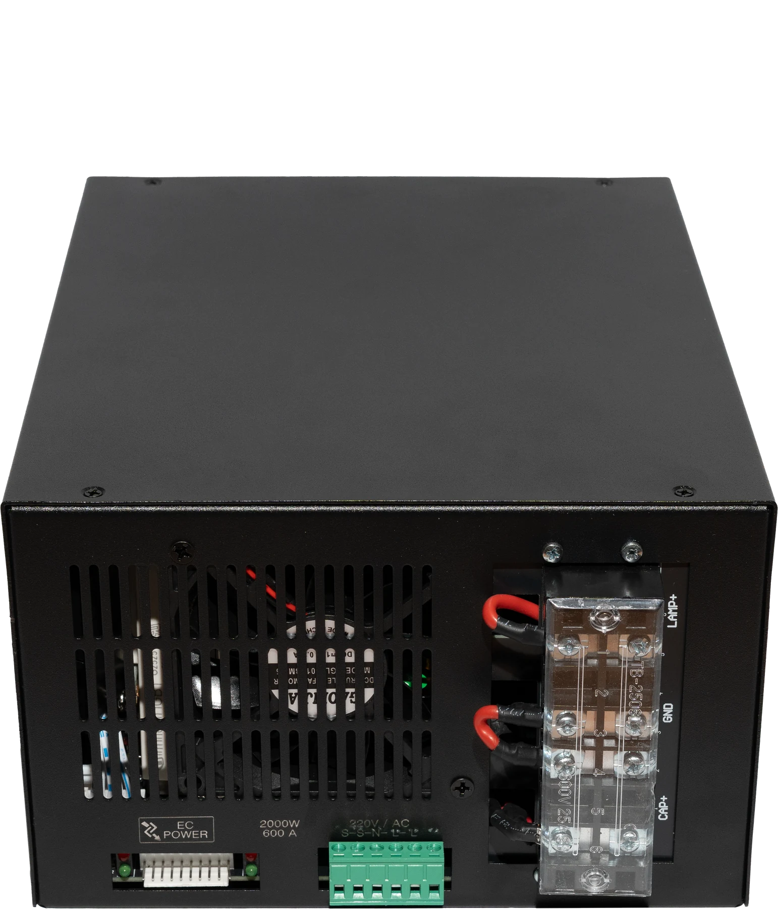
What is inside the enclosure?
Photographs show an actual unit from the production line.
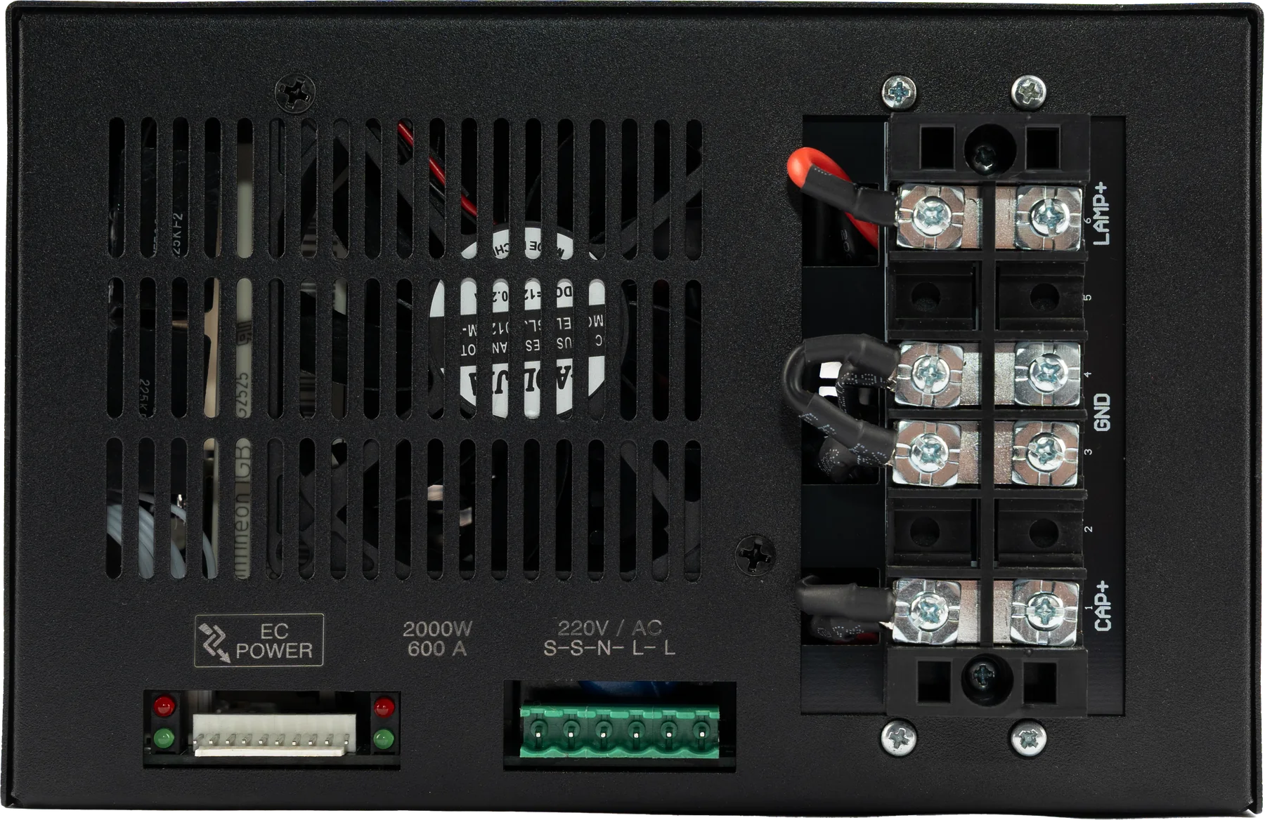
Connections and terminals
How does it connect to the system?
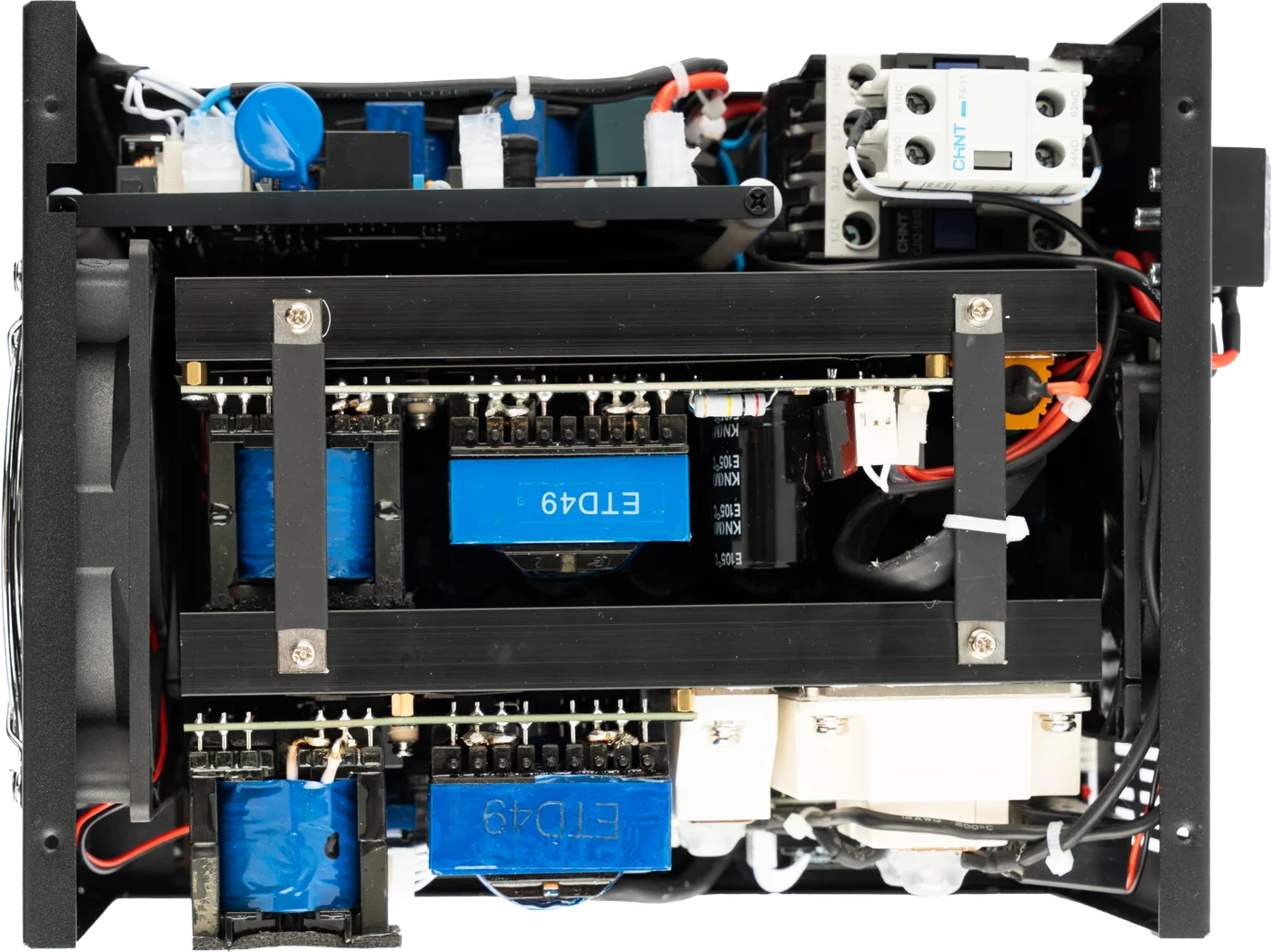
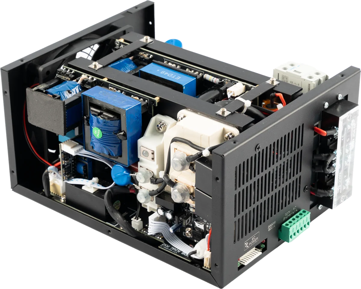
Every connection is gathered on the rear panel. Power terminals and the control interface sit in separate zones, so the wiring stays clear.
 123456
- Mains input (S-S-N-L-L)220 V AC supply through the six-way green terminal block. From left to right the poles are S-S, the run switch input, N for neutral and L-L for line. The unit stays dead unless S-S is bridged, and the line is pulled with two separate cables so the current is not concentrated on a single pole. A 10 A fuse and at least 1.5 mm² cable are recommended.
- Control interface10-pin connector carrying the output voltage reference plus charge, simmer and run commands. Status LEDs sit beside it.
- LAMP+ / LAMP−Xenon lamp output. Pulse current is delivered through these terminals.
- GNDChassis and reference earth point. Connection is mandatory for safe operation.
- CAP+ / CAP−Capacitor connection. The capacitor ships with the unit: 22000 µF / 450 V, two pieces for the 2000 W class and one for the 1200 W class.
- Ventilation and fanForced air outlet. Airflow must not be obstructed during installation.
Connection diagram
How do energy and control flow?
Follow, step by step, where IPL POWER sits inside your device. The numbers on the diagram match the terminals in the connection photograph above.
1 / 5
10-pin control interface
- Vref2.78-5.49 V ⇄ 200-400 V
- Chargecapacitor charge command
- Simmerlamp kept conductive
- Runpulse trigger
- Feedbackcharge and simmer status
- +12 Vcontrol supply
The diagram is simplified to explain system integration; it does not show the internal circuitry of the unit. Cable cross-sections, protective devices and the final operating point are engineered according to the ECP-2000 user manual.
Technical architecture
IPL POWER technical specifications
Choose a configuration from the product family. The technical values below update with your selection.
Selected model
IP-2000W600
2000 W energy class
200-400 V DCOutput voltage
Max. 600 APeak current
Max. 2000 WOutput power
The main model of the family. The values in the ECP-2000 user manual and in the CE, EMC and LVD files belong to this model.
Electrical
- Input voltage
- 220 V AC (±10%)
- Input frequency
- 50-60 Hz
- Output voltageModel-dependent
- 200-400 V DC
- Output powerModel-dependent
- Max. 2000 W
- Peak currentModel-dependent
- Max. 600 A
Pulse and control
- Output frequency
- 1-10 Hz, adjustable
- Voltage control input
- 2.78-5.49 V for 200-400 V
- Control functions
- Charge, simmer and run
- Feedback
- Charge and simmer status outputs
- Control supply
- +12 V DC output
Mechanical and environment
- Dimensions
- 270 × 195 × 125.1 mm
- Weight
- 5.4 kg
- Thermal protection
- 65 °C
- Operating temperature
- -20 to 50 °C
- Insulation resistance
- >20 MΩ
Rows marked model-dependent follow the model selected above. All other values and the mechanical figures are sourced from the 2026 ECP-2000 (IP-2000W600) user manual; enclosure size and weight for the 1200 W class are confirmed at quotation. Peak current is xenon-lamp dependent, and the final operating point must be verified with the lamp, capacitor and device architecture.
Integration
Planned around your device architecture.
01
Power connection
Integrated with a 200-240 V AC input, external on-off connection (S-S) and protective earth. The input block is arranged S-S-N-L-L, and line is pulled to the L-L poles with two separate cables. A 10 A input fuse and at least 1.5 mm² cable are recommended.
02
Energy path
Connects to the xenon lamp and to the 22000 µF / 450 V capacitor supplied with the unit, through the LAMP+, LAMP−, CAP+ and CAP− terminals.
03
Control interface
The 10-pin interface carries voltage control, charge, simmer and run commands plus status feedback.
Model family
All configurations side by side
One shared architecture, different output classes. Selecting a model also updates the technical specification section.
| Model | Output voltage | Peak current | Output power | Class |
|---|---|---|---|---|
| 200-400 V DC | Max. 600 A | Max. 2000 W | 2000 W energy class Reference model | |
| 200-400 V DC | Max. 400 A | Max. 1200 W | 1200 W energy class |
What ships with it
The capacitor ships with the unit.
You do not have to source the capacitor that delivers pulse energy to the lamp; it is supplied together with IPL POWER. Two pieces with the 2000 W model, one with the 1200 W model.
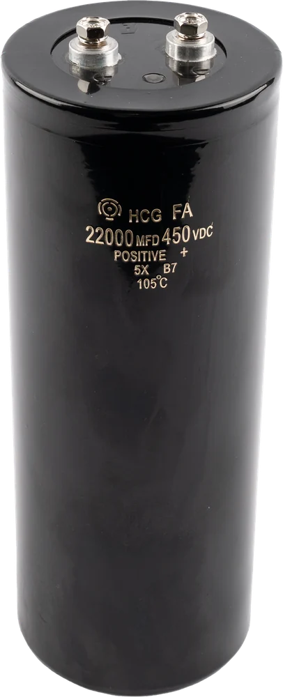
- Type
- Electrolytic, screw terminal (HCG FA)
- Capacitance
- 22000 µF
- Voltage
- 450 V DC
- Temperature class
- 105 °C
- 2000 W unit
- 2 pieces
- 1200 W unit
- 1 piece
The bank is mounted outside the unit, inside the device enclosure, and connects through the CAP+ and CAP− terminals. Cable size and placement are planned together during integration.
Quality and documents
Verified product documentation.
Document scope is checked against the model and configuration. Current copies are shared on request.
Verified
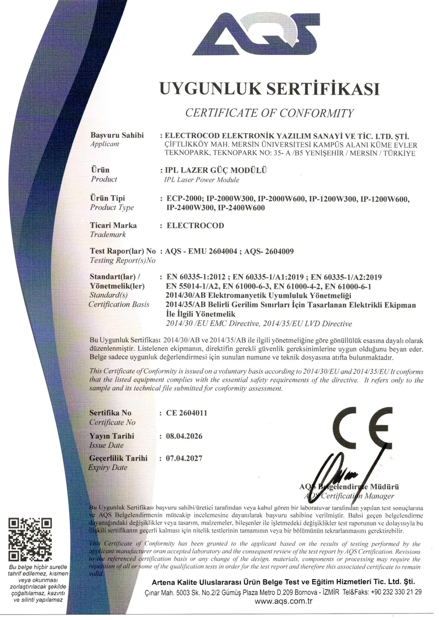
CE certificate of conformity
CE 2604011 · issued 08.04.2026 · valid to 07.04.2027 · scope: ECP-2000, IP-2000W300/W600, IP-1200W300/W600, IP-2400W300/W600
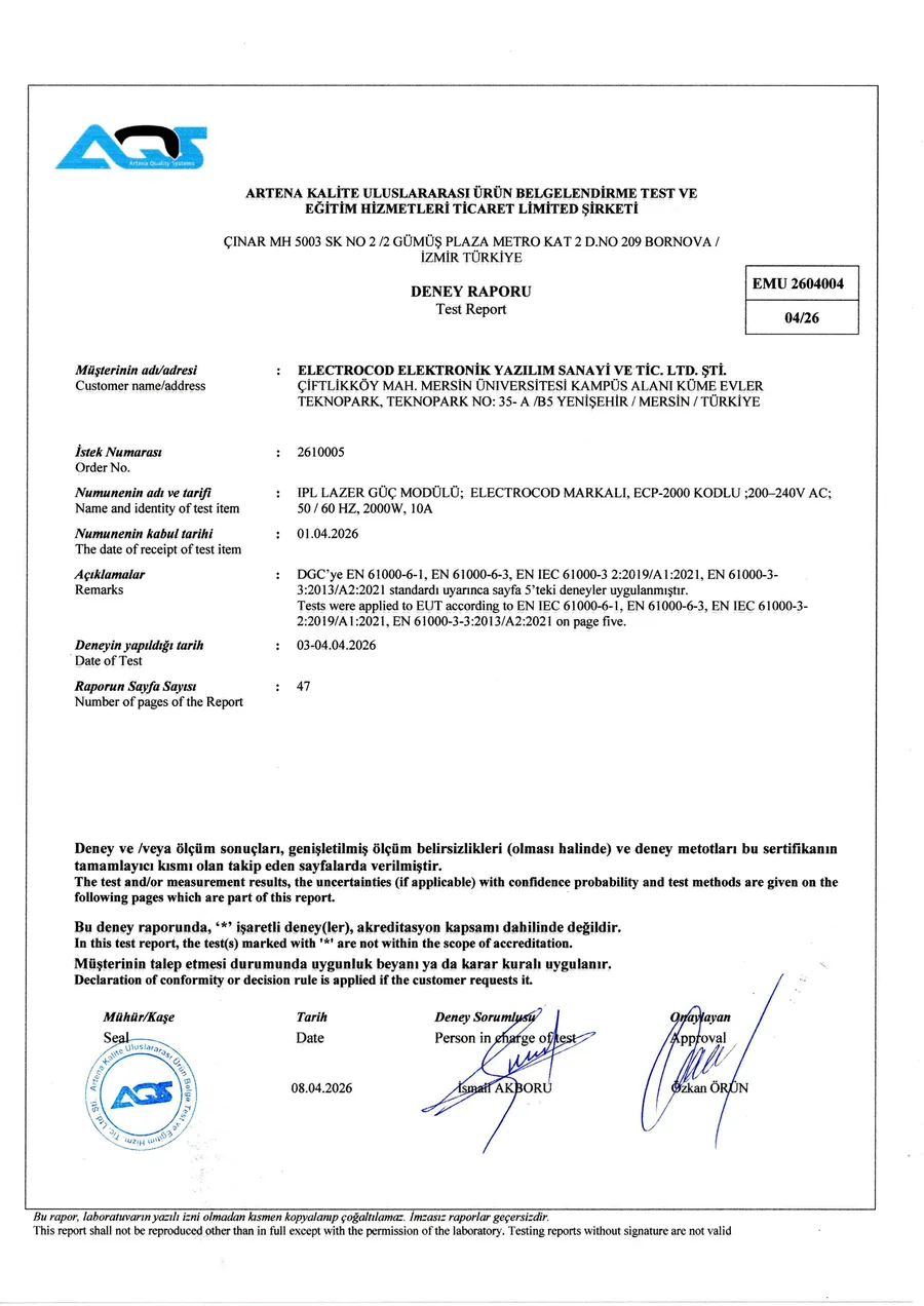
Verified
EMC test report
AQS-EMU 2604004 · 47 pages · emission and immunity tests passed
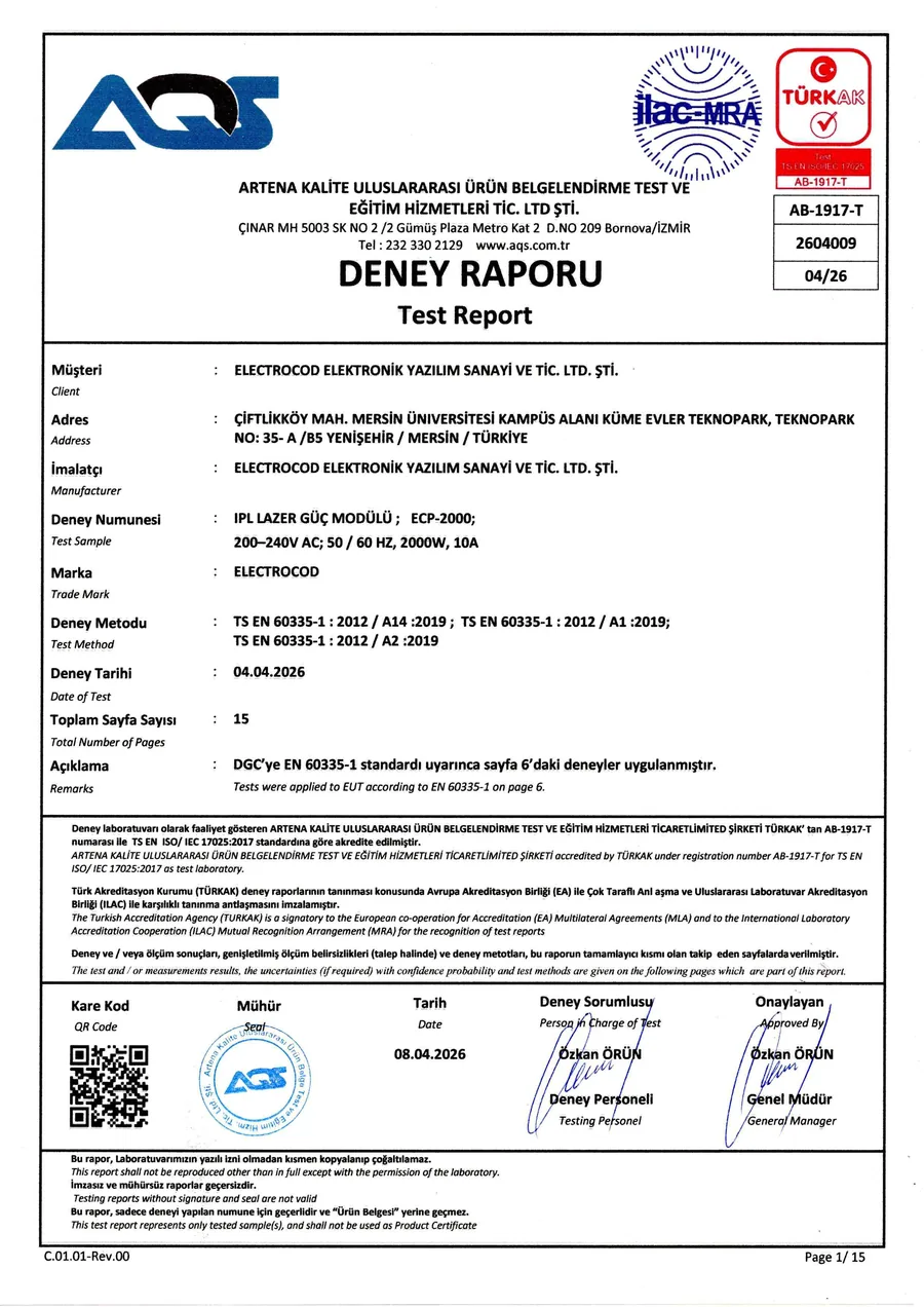
Verified
LVD test report
AQS-2604009 · 15 pages · electrical safety tests passed
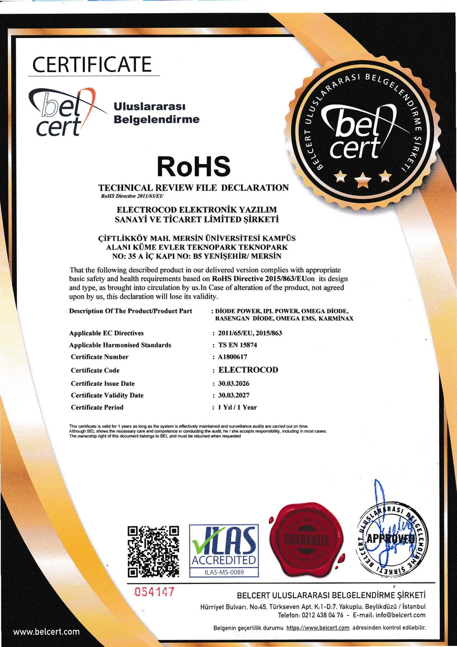
Verified
RoHS declaration
Technical file declaration under 2011/65/EU and 2015/863
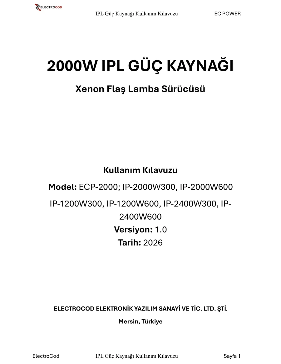
Downloadable
User manual
ECP-2000 · 14 pages · V1.0 (2026) · Turkish and English
Frequently asked
What buyers ask before integration
Does the IPL power supply come with the capacitor?
Yes. The capacitor that delivers the pulse energy to the lamp ships with the unit: 22000 µF / 450 V, screw-terminal electrolytic type. Two are supplied with the 2000 W model and one with the 1200 W model. The capacitor sits outside the unit, inside the device enclosure, and connects to the CAP+ / CAP− terminals.
How is the output voltage set?
The charging voltage is adjustable between 200 and 400 V DC. Your device's own control board sets the level: a 2.78-5.49 V analogue reference on the 10-pin interface maps to that range. Charge, simmer and run commands arrive over the same interface, and the charge and simmer status feedback is read from it.
Which xenon lamps does it work with?
The unit delivers up to 600 A peak current (400 A on the 1200 W model). The actual peak current depends on the xenon lamp you connect, so the final operating point is verified together with the lamp, the capacitor and your device architecture. Share the lamp type and we will define the right configuration with you.
Does the unit have certification?
Yes. A CE declaration of conformity (CE 2604011), an EMC test report (AQS-EMU 2604004), an LVD test report (AQS-2604009) and a RoHS technical file declaration are available. The EMC and LVD tests were carried out in a TÜRKAK accredited laboratory. Current copies are shared on request.
Other products
Explore the other power families
 DIODE POWER
 EMS POWER
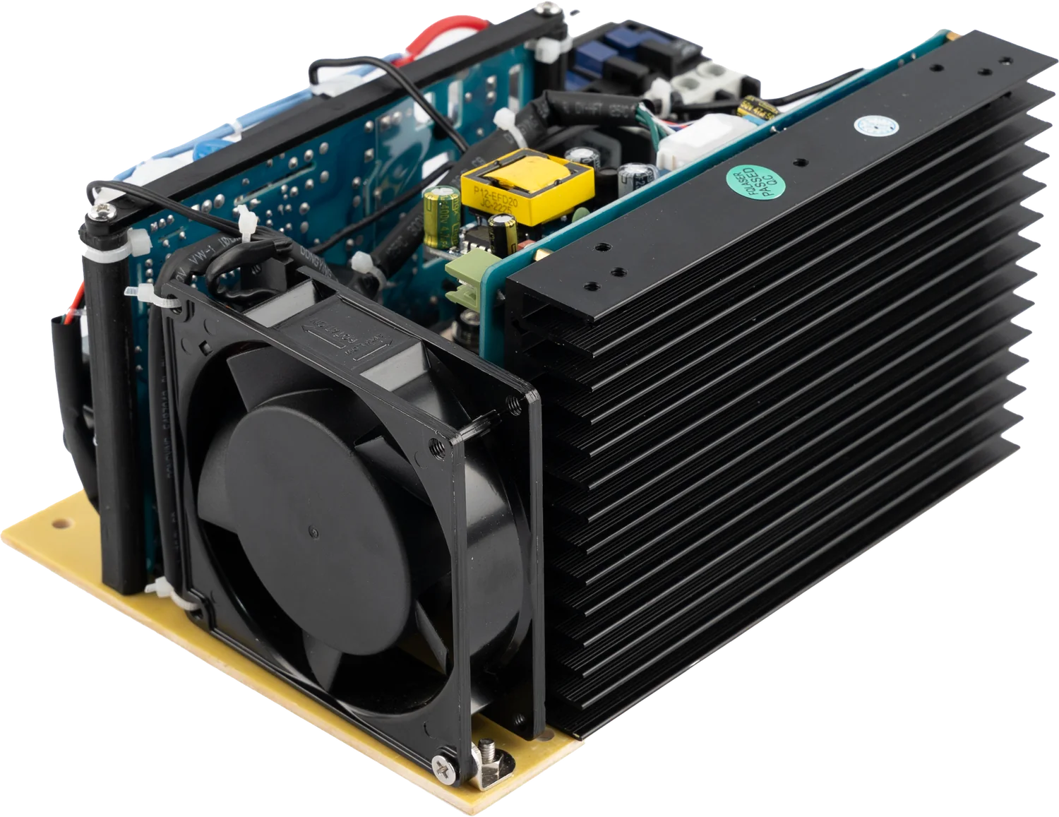 ND-YAG / Q-SWITCH POWER
Let us define the right power architecture for your device.
Share the device type, target values and quantity. Our technical team will respond with the suitable product and integration options.