
Power board for body slimming and muscle toning devicesEMS POWER
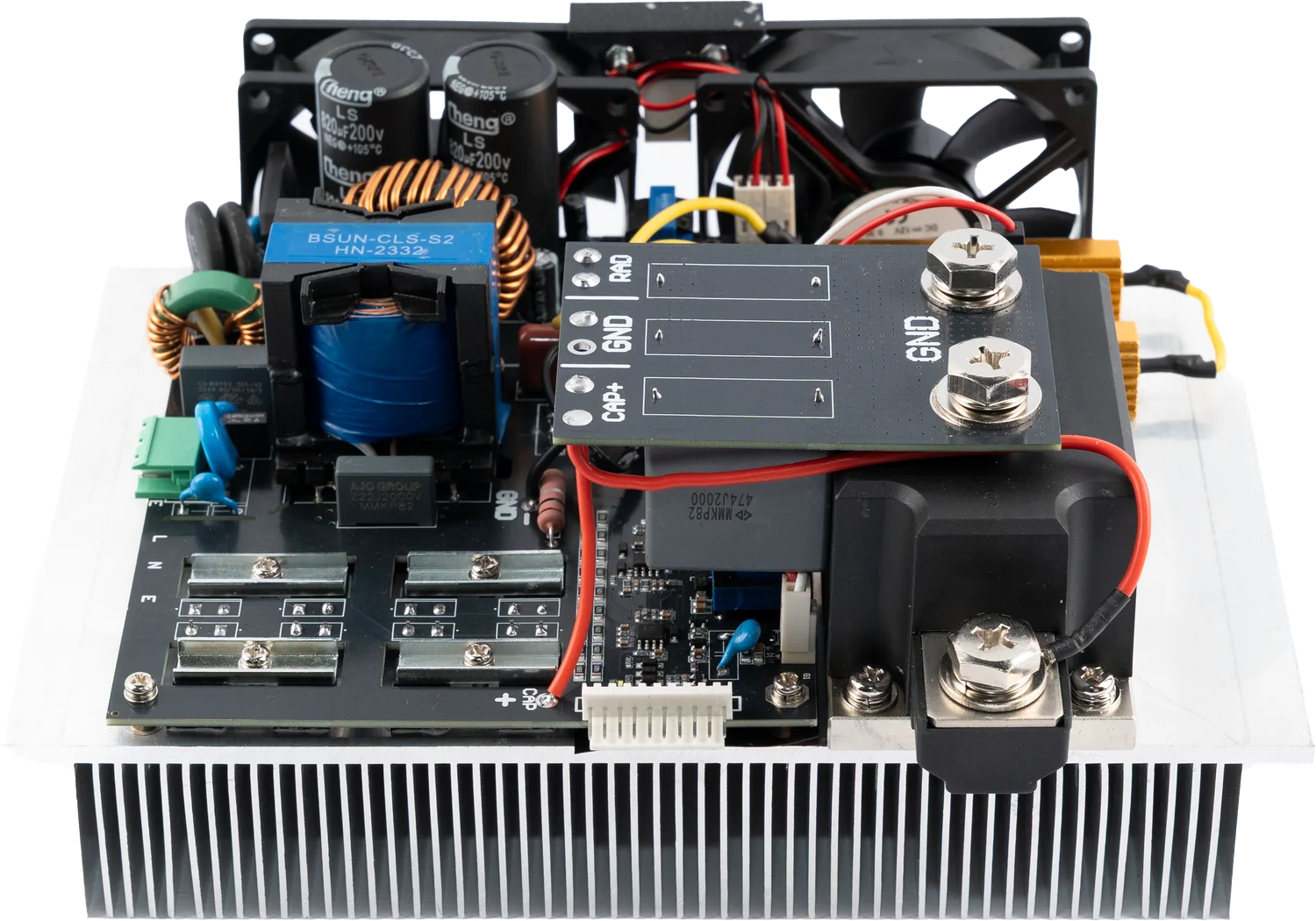
The power board of slimming and muscle-building devices built on EMS and HIFEM technology. It drives two coils independently, runs the pulse program and monitors coil temperature.
220 V ACInput
2 independentChannels
80 µF / 2000 VPulse capacitor
Open frame, OEMForm
Product capability
Power electronics engineered for system integration.
Two coils, controlled independently.
In EMS and HIFEM devices the muscle contraction comes from magnetic field pulses produced by a coil. EMS POWER generates those pulses, runs the two channels separately and reports coil temperature back to the device controller. The board is open-frame and mounts inside your own enclosure.
The open-frame board. The power stage sits on the heatsink block, with both channel output terminals on the right.
Inside the unit
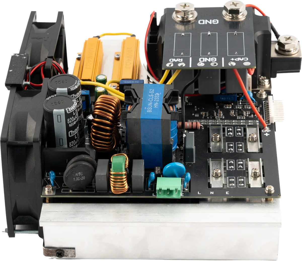
What is inside the enclosure?
Photographs show an actual unit from the production line.
Connections and terminals
How does it connect to the system?
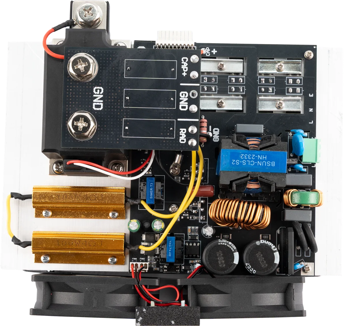
The board ships open-frame; the connection layout is planned together, around the internal design of your device. The numbers mark the connection zones on the board and match the numbers in the connection diagram below.
1234- Mains input (L / N / E)The board is supplied from 220 V AC. The protective earth (E) connection is mandatory for safe operation; as the board is open-frame, earth continuity runs through the device chassis and is verified at device level.
- Control interfaceLink to the device controller. Pulse program, channel selection and treatment intensity are sent over this line; coil temperature, ready and fault states are read back through the same interface.
- Capacitor connectionWhere the 80 µF / 2000 V DC film capacitor supplied with the board connects; charging runs over this line. Being film type, it is non-polar and has no plus-minus orientation.
- Applicator outputThe switched output the coil head connects to. Pulse current is delivered through these terminals; the second channel is wired the same way.
Connection diagram
How does the pulse energy reach the coil?
Follow, step by step, where EMS POWER sits inside your device. The numbers mark the connection zones on the board. One channel is drawn; the second channel is wired the same way.
1 / 5
Functions running on the control interface
- Pulse programpulse width and rate
- Channel selecttwo independent channels
- Intensitytreatment level
- Triggerpulse command
- Temperaturecoil temperature feedback
- Statusready and fault information
The diagram is simplified to explain system integration; it does not show the internal circuitry of the board. Interface signals, cable cross-sections, protective devices and the final operating point are defined per project once the coil, the capacitor and the device architecture are verified.
Technical architecture
EMS POWER technical specifications
Electrical values
- Input voltage
- 220 V AC · L / N / E
- Input frequency
- 50-60 Hz
- Pulse capacitor
- 80 µF / 2000 V DC · film (SH) · 1 piece
- Pulse energy
- ≤160 J at 2000 V (theoretical maximum)
- Channels
- 2 independent channels
- Input stage
- EMI filter · NTC soft start
Pulse and control
- Output topology
- Resonant capacitor discharge into the coil
- Pulse width
- Coil-dependent · ≈ 220-350 µs for 60-150 µH
- Peak current
- ≈ 1.5-2.3 kA over the same range
- Intensity control
- Set by charge voltage; energy scales with its square
- Thermal monitoring
- Coil temperature feedback
- Repetition rate (device)
- Program-driven; limited by average charge power
Safety, cooling and OEM
- Bleeder resistors
- 2 × 100 W · separate RAD terminal
- Cooling
- Fan-cooled heatsink block · 2 fan outputs
- Connections
- CAP+ / GND screw bus · L / N / E terminal block
- Earthing
- Through the device chassis, verified at device level
- Delivery form
- Open-frame board with capacitor
- Document scope
- CE · EMC · LVD (TS EN 60335-1)
The values in this table come from three sources. First, the ratings of the components actually used on the board: the pulse capacitor, the bleeder resistors, the input stage and the connection hardware. Second, quantities calculated from those ratings: the energy an 80 µF capacitor holds at 2000 V, and the pulse width and peak current that follow from a resonant discharge into the coil. Pulse width and peak current depend on the coil as much as on the board, so they are given for a common inductance range — with a 114 µH coil the pulse lands close to the 300 µs figure familiar from HIFEM applications. Third, the rows marked "device" describe how the EMS / HIFEM devices this board feeds actually run. A model-specific user manual and test report for EMS POWER have not been published yet; the guaranteed operating point is defined per project once the coil, capacitor and device architecture are verified.
Integration
Planned around your device architecture.
01
Coil characterisation
Coil inductance, resistance, target field and duty cycle are evaluated technically.
02
Thermal architecture
Coil sensors, air or liquid cooling and safe shutdown thresholds are planned with the device.
03
Control program
Channel sequence, pulse program, session behaviour and user-interface commands are adapted to the OEM software.
Model family
EMS POWER product family
This product is offered as a single configuration; output values are engineered around your device architecture.
EMS POWER
Dual-channel open-frame power board
OEM configuration
Engineered for the coil and device architecture
What ships with it
One pulse capacitor is supplied with the board.
The pulse energy that drives the coil is stored in this capacitor. It is a high-voltage film type rather than an electrolytic one, selected for pulsed operation and built to ELECTROCOD specification.
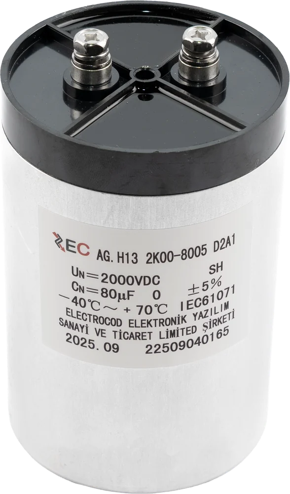
- Type
- Film, self-healing (SH)
- Capacitance
- 80 µF ±5%
- Voltage
- 2000 V DC
- Operating temperature
- −40 °C … +70 °C
- Standard
- IEC 61071
- Quantity
- 1 piece
The label is printed in the ELECTROCOD name; the capacitor is sourced to values we define. If the coil inductance or the target pulse energy changes, the capacitance is re-specified per project.
Quality and documents
Verified product documentation.
Document scope is checked against the model and configuration. Current copies are shared on request.
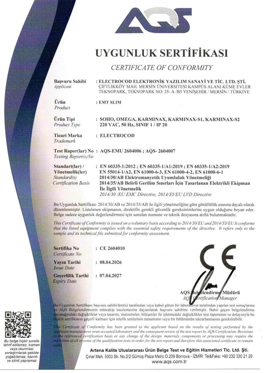
Verified
CE certificate of conformity
CE 2604010 · issued 08.04.2026 · valid to 07.04.2027 · scope: EMT SLIM · SOHO, OMEGA, KARMINAX, KARMINAX-S1, KARMINAX-S2
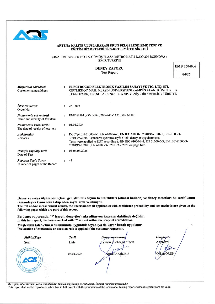
Verified
EMC test report
AQS-EMU 2604006 · 43 pages · emission and immunity tests passed
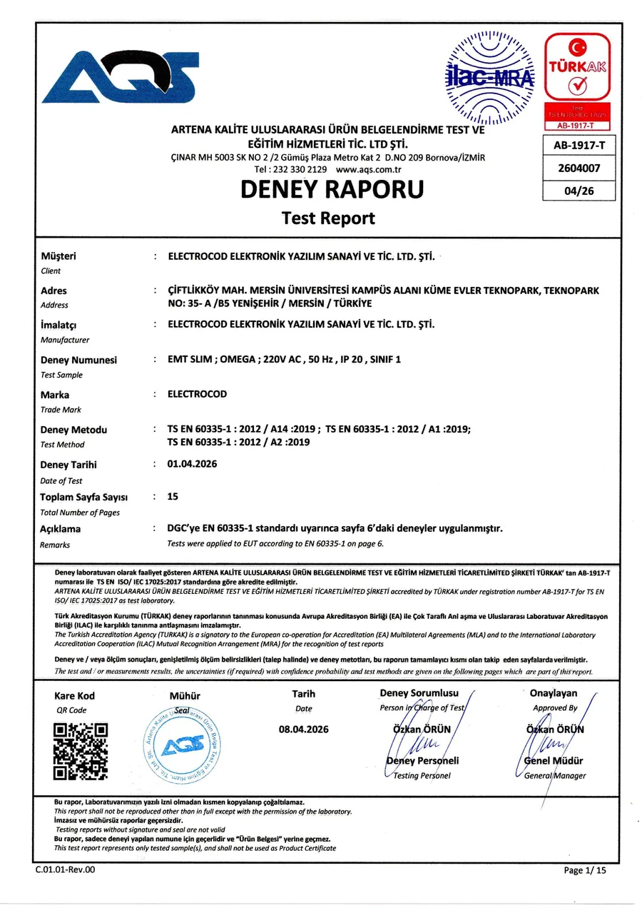
Verified
LVD test report
AQS-2604007 · 15 pages · TS EN 60335-1 · TÜRKAK accredited laboratory
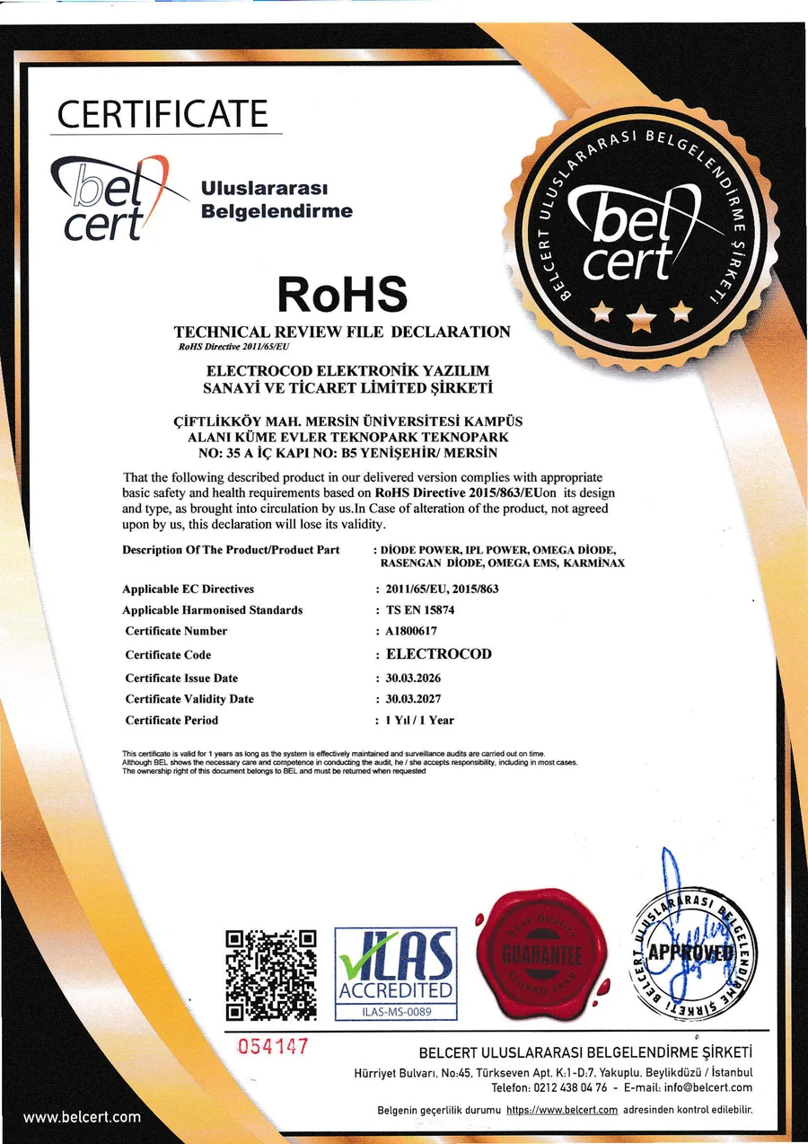
Verified
RoHS declaration
A1800617 · technical file declaration under 2011/65/EU and 2015/863
Frequently asked
What buyers ask before integration
Which coils does the board work with?
The coil defines the board's operating point. Across a 60-150 µH inductance range the pulse lasts roughly 220-350 µs with a peak current of roughly 1.5-2.3 kA. At the start of a project we review coil inductance, resistance, target field strength and duty cycle together.
Are the two channels really independent?
Yes. The board drives two coils independently, and the channel sequence and pulse programme are adapted to your OEM firmware. That lets you run two applicators simultaneously or alternately.
Is coil temperature monitored?
Yes. Coil temperature feedback is reported to the device controller. Sensor placement, the air or liquid cooling arrangement and safe-stop thresholds are planned together with the device. The board's own heatsink is fan cooled and provides two fan outputs.
How is pulse intensity set?
Intensity is set through the charging voltage of the pulse capacitor. Because energy rises with the square of the voltage, a small voltage change makes a clear difference in intensity. The capacitor is an 80 µF / 2000 V film type; at 2000 V the theoretical upper limit is 160 J.
Other products
Explore the other power families
 IPL POWER
 DIODE POWER
 ND-YAG / Q-SWITCH POWER
Let us define the right power architecture for your device.
Share the device type, target values and quantity. Our technical team will respond with the suitable product and integration options.